Enterprise grade servers tend to have an embedded computer that keeps track of the server's status even when it's turned off. This sort of thing is called "out of band management". Now that we're fully in the "internet of things" era, there's really no reason why we can't all have the benefits of such a system. In this article, I'll document my "system monitor" that keeps track of my primary PC, even when I'm not around.
The Problem
My primary PC sits under my desk in my office. I'm often elsewhere in the house, streaming games to my laptop with Steam's In-Home Streaming. Sometimes, my PC goes to sleep, or it gets on the wrong app and just needs a quick Alt-Tab. Also, since I'm not near it, I rarely know what the state of the CPU and RAM is. Can I turn the settings up in my game? Or is my rig tapped out?
Alternate Solutions
I could go with an "in band" management tool, like RDP or VNC. However, these don't work well with games. If there's a full screen, high frame rate app running, they tend to run super slow. RDP also locks the screen when I disconnect unless I jump through some hoops.
Some of these things I could take care of with a keyboard/mouse sharing app like Synergy. However, I often can't see the screen directly, which makes it hard to control with my local keyboard and mouse. Also, I've had some stability problems in the past with it.
Wake on LAN solves the "my machine's asleep" problem, although it doesn't do anything else. It also is kind of sketchy on wireless networks, although I have had it work on certain devices before.
If this box ran Linux, I could SSH in and get at least some of these things done. However, it doesn't, and can't because it's a gaming rig and has to handle a bajillion different games. Maybe someday SteamOS or similar will catch up to Windows and I can finally ditch the OS... but that future's kind of a ways off at this point.
My Solution
What I want to build is a device that connects over USB to my PC, and is capable of monitoring the system and doing some basic interactions with it. I want it to work as independently of the PC as possible, and I'd like it to have its own IP and UI separate from my PC's OS. That way, I can wake the machine and put it to sleep.
I designed this project around the Digistump Oak, which is a ESP8266-based board. That means it's got a fair amount of processing power plus a WiFi radio. The only downside to the Oak is that although it has a USB port, it's for power only. So, I'll need some sort of interface to connect it to the computer. For this, I'm going to use a Sparkfun Pro Micro.
The hardware side of the equation ought to be pretty straightforward, but there's going to be quite a lot of software to work on here. I'll need to write a full stack - from low-level firmware all the way up to front-end UI in Javascript and HTML5.
# Next: Parts List and Board Layout
Hardware
Parts List
- Digistump Oak
- SparkFun Arduino Pro Micro (3.3v)
- BusBoard SB400 Solderable Breadboard
- Hammond "AS" Size Project Box
- 2x 4.7kOhm resistors
- Some jumper wire, solder, etc
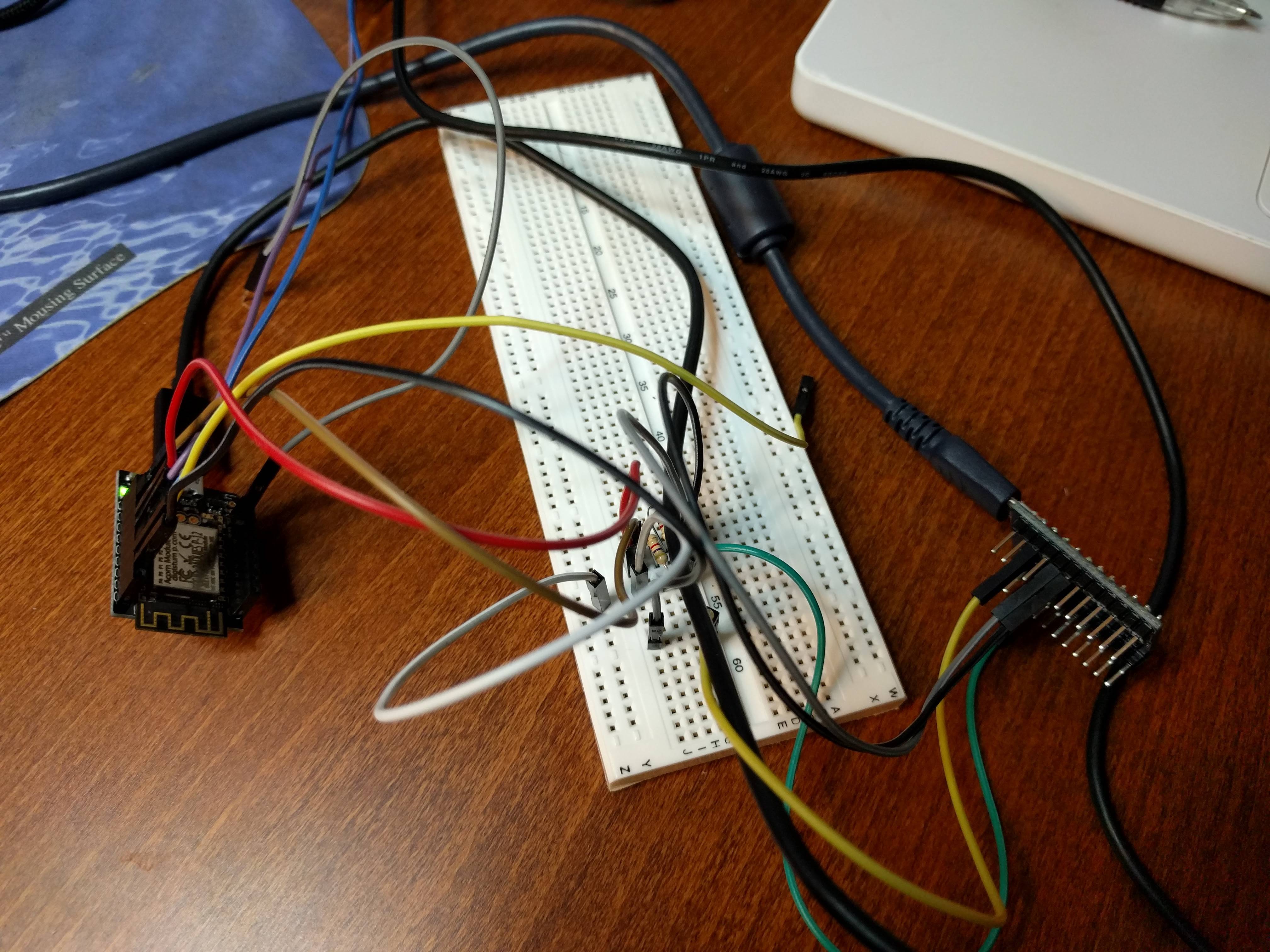
This project is a combo of a couple of boards, as I mentioned in the previous section. I'll take each board individually in the coming sections. The rest of this stuff you can get off of Amazon, or your favorite electronics supply house. I used a solderable breadboard for this, although you could wire the boards directly together if you wanted, or you could get a custom board built. It used to be much harder to come by solderable breadboards, but for $5 on Amazon you can have some pretty nice ones shipped!
Digistump Oak
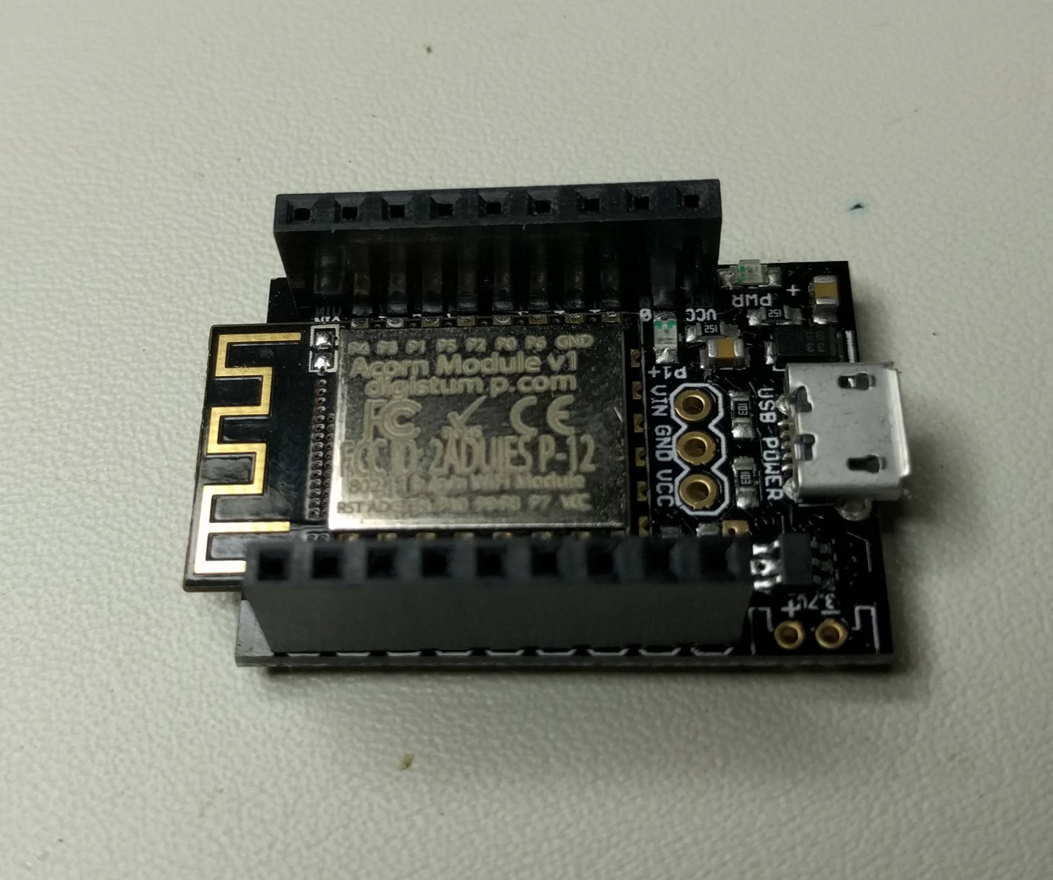
The Digistump Oak is basically an ESP8266-based module. There are a variety of ESP8266 boards out there, but I backed the Oak on Kickstarter so I had a set of 3 of them to play with. The Oak is designed around "shields," much like the Arduino. There's support for programming it via the Arduino IDE, so you can use Processing if that appeals to you.
Also, the Oak is supported by the Particle Cloud, although there are still features missing from the integration. For the most part, the Particle Cloud is just a way to flash the board without hooking the Oak directly to a PC. The Arduino IDE uploads the firmware to the cloud, and the Oak checks periodically to see if there is a new firmware image available. It flashes the new image, and then reboots to load it.
It's probably one of the more inexpensive user-friendly ESP8266 boards around, but everybody's probably got their own favorite variant, so if something else appeals to you, knock yourself out.
SparkFun Pro Micro
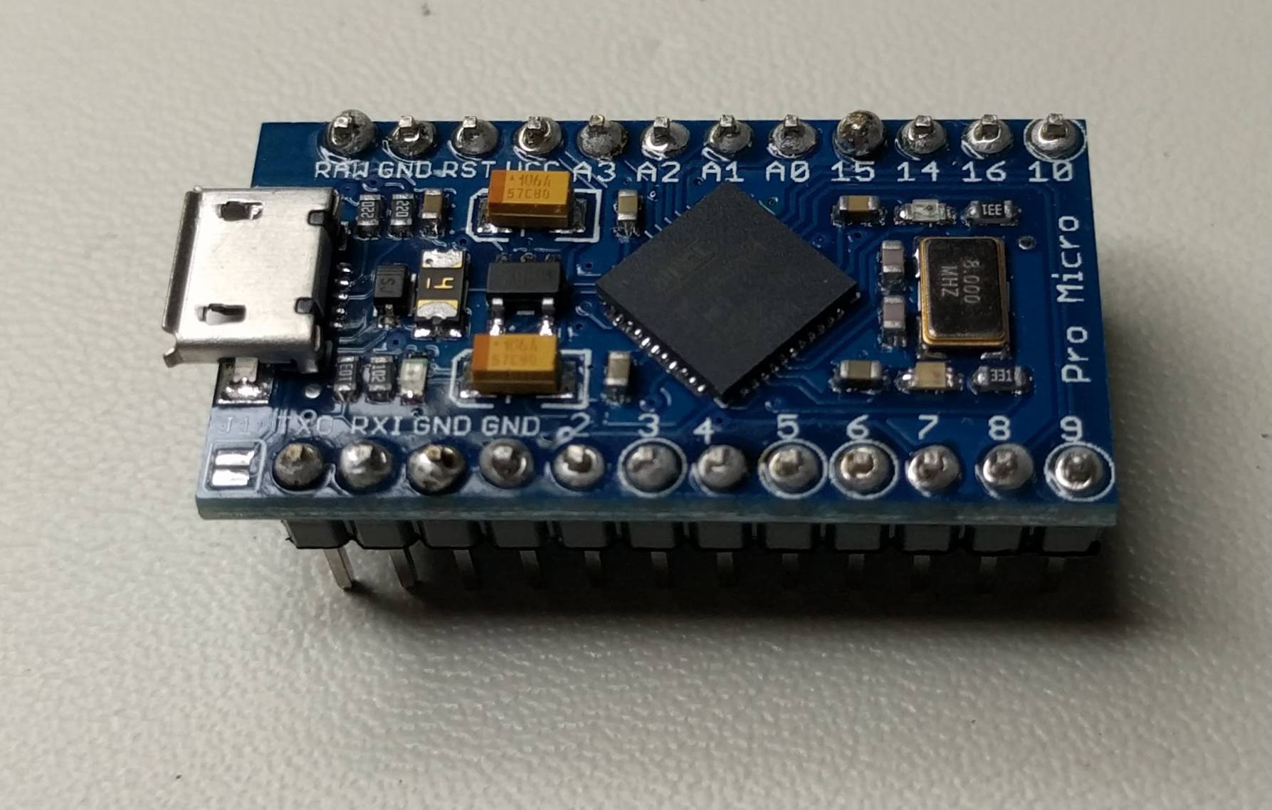
The SparkFun Pro Micro is based around an Atmel ATmega32U4 microcontroller. The major advantage to this chip over similar micros is that it has a dedicated, hardware USB interface. Many other Atmel chips can emulate USB, but the 32U4 actually has full support for it. This means that you can enumerate the Pro Micro as a USB device and have it behave as both a serial port and a keyboard, with a high degree of reliability.
One other requirement I have for my Pro Micro is that I wanted to use the 3.3v variant. That way, I don't have to do logic level conversion between the Pro Micro and the Oak, which is a 3.3v board. In some cases, this wouldn't matter, but it doesn't really seem like the Oak's 3.3v is recognized as "high" by the 5v Pro Micro. If you've got to use a 5v version of the board, SparkFun also sells 3.3v to 5v Logic Level Converters.
It also helps that this is a rather inexpensive board, and you can buy clones for $5 or so on eBay. Do be careful with these knock-offs though! I ordered a set of 3.3v boards from China via eBay, and when they arrived weeks later, they were actually 5v boards! I'm glad I had the foresight to test them before hooking everything up, or I could have fried something. Luckily, eBay refunded my money after I showed them the product was mislabeled on the site. If you decide to go the eBay route, check the listing, and make sure they're selling the 3.3v/8MHz version.
Board Layout
There are a couple of interfaces I could have used for board-to-board communication. Both the Pro Micro and the Oak support SPI and I2C. I2C uses fewer pins, so I opted to go that route. I2C requires that you pull the data and clock lines to Vcc with pullups, and the standard recommendation is to use 4.7kOhm resistors for this task.
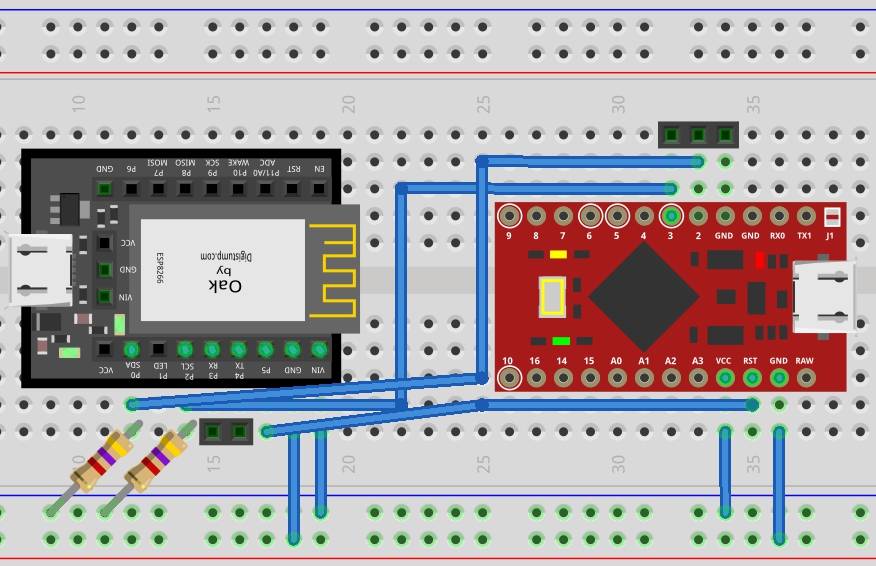
Another board layout consideration is how power should be routed around the board. Both the Oak and the Pro Micro have 3.3v voltage regulators, so either board could accept the 5v from the USB port. The Pro Micro has to be connected to USB for data, so we might as well let it power the Oak.
Design Decision Both boards have "raw" voltage pins that can accept or drive 5v, and both can also accept or drive regulated 3.3v. I opted to connect the 3.3v output from the Pro Micro to the 3.3v on the Oak. This is probably not the "best" way to do it - I'd think that someone who does this for a living would suggest that you hook up the USB 5v to the Oak's raw voltage in, because that way you're making use of both regulators. However, there's enough leftover capacity in the voltage regulator on the Pro Micro that I don't have any stability issues owing to my decision. Also, this means that "high" voltage on both boards is identical, although I'm not sure that that means much.
I also decided that I might want to reset the Pro Micro from the Oak's web interface, so I opted to hook the Reset pin on the Pro Micro to a GPIO on the Oak. Should the USB interface get into a bad state, or the Pro Micro crashes for whatever reason, I don't have to pull power as long as the Oak is still alive.
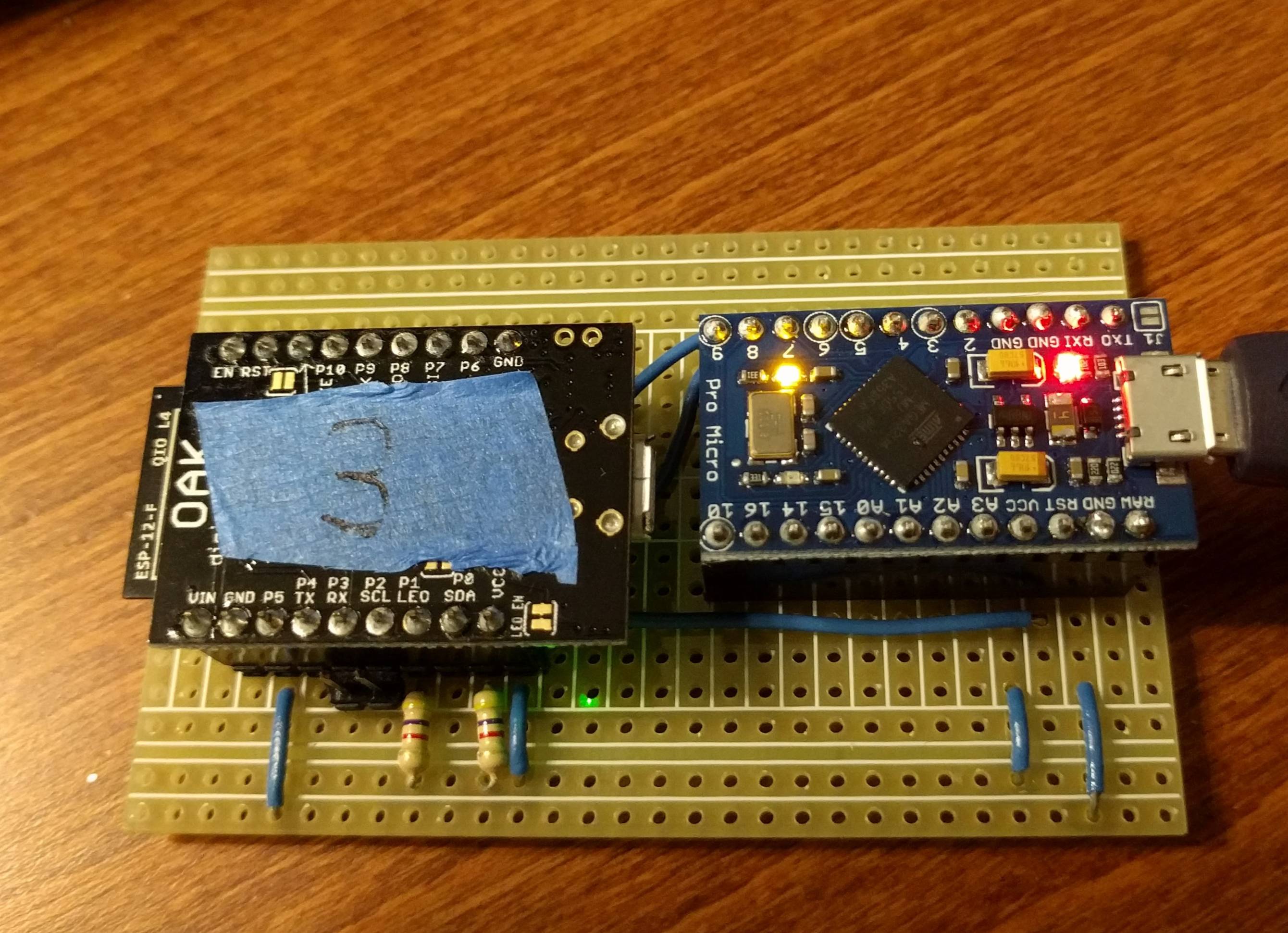
I added a few headers to the board. The ones next to the Oak are for the Oak's serial port, so that I can do debug if need be. The ones next to the Pro Micro are also for the Oak - they were just more convenient to place there. The Oak has a "safe mode" that it can be put into where it waits for a flash download over serial. Taking the SDA pin to ground at boot triggers this. That way, if things go horribly wrong, I don't have to take the Oak completely out and rewire it up to reflash it.
Since I'm basically just jamming two premade, tested boards together like a couple of LEGO bricks, there's not a lot of complexity to the hardware. The software, on the other hand, is a whole different story.
# Next: Monitored PC Software
Let's take this part by part and work our way through the whole stack. I'll start with the monitored PC side, and then work my way through to the code that executes in the browser.
# Monitored PC Code
The monitored PC's code has the following tasks:
- Collect performance information
- Report performance information to the Pro Micro via USB
- Accept input from the Pro Micro via USB
The USB tasks are simplified by the Pro Micro's USB support. We can use the USB serial port on the Pro Micro to send the performance info, and the keyboard interface makes accepting input a snap. So that simplifies these requirements down to "get current state of machine" and "write to a serial port."
I decided to use Python for this, since it's an easy language to write, I know it well, and there are tons of libraries for doing common tasks. It's also cross platform, which means that although I'm writing this for Windows, porting it to a Linux or OSX system should be easy.

The two packages I pulled in are:
Here's the critical loop of the code, but the whole thing is up on GitHub:
def run(self):
	# the first time, this does nothing
	psutil.cpu_percent()
	time.sleep(.5)
	report_end = bytearray(1)

	while(self.running):
		if(self.ser == None):
			self.reset_port()
			if(self.ser == None):
				time.sleep(5)
				continue
		report_dict = {}

		# get the timestamp
		report_dict['t'] = time.strftime("%Y-%m-%d %H:%M:%S")

		# Get CPU usage
		cpu_pct = psutil.cpu_percent(percpu=True)
		report_dict['c'] = []
		for i in range(len(cpu_pct)):
			report_dict['c'].append(cpu_pct[i])

		# Get memory usage
		mem = psutil.virtual_memory()
		report_dict['m'] = {'t':mem.total, 'a':mem.available}

		# Get disk usage
		diskparts = psutil.disk_partitions()
		report_dict['d'] = []
		# print diskparts
		for part in diskparts:
			if os.name == 'nt':
				if 'cdrom' in part.opts or part.fstype == '':
					# skip optical drives on windows
					continue
			usage = psutil.disk_usage(part.mountpoint)
			report_dict['d'].append({'m':part.mountpoint, 't':usage.total, 'u':usage.used})


		# Serialize to JSON
		report = json.dumps(report_dict)
		print report
		# Write to the serial port
		try:
			self.ser.write(report)
			self.ser.write(report_end)
		except serial.SerialException:
			print("Can't write to serial port, trying to reopen...")
			self.reset_port()

		time.sleep(5)
As you can see, most of the loop is fetching the current statistics from psutil's functions, and then I create a Python dict out of these values. The dict has entries for the current time ('t'), the current CPU usage, per core ('c'), memory stats ('m'), and disk utilization ('d').
Design Decision From there, I decided to convert this dict to text using JSON. JSON is a great text format for data like this, and the fact that it's natively supported in JavaScript will save us some pain later when I want to parse it for the browser. With the data pre-formatted, I can just funnel it through the system without having to parse it again. That will save CPU time and keep the complexity of the later code to a minimum. JSON has a bit of overhead - though far less than XML - but in my testing it wasn't significant enough to really matter.
One thing I'd like to add to this is a tray icon or something similar. Right now it just runs in a terminal/DOS prompt. There's an example of making a Python script with a tray icon which is cross platform, over on Stack Exchange.
# Next: Pro Micro & Oak Firmware
# Pro Micro Code
In my setup, the Oak is the I2C master, and the Pro Micro is the I2C slave. The Pro Micro handles mostly "middleman" tasks:
- Accept and store report data via USB (Serial)
- Transmit commands via USB (Keyboard)
- Communicate with the Oak via I2C to get keyboard commands
- Communicate the report data to the Oak, also via I2C
This doesn't sound too bad, but there are plenty of gotchas despite the low number of lines of code to be written.
Arduino IDE Warning There are two Pro Micro boards in the Arduino IDE. One is for the 5v variant, and one is for the 3.3v variant. If you use the wrong one, the board will boot but fail to load, and you'll get a "Device Not Recognized" error if you're hooking up to Windows. There's a fix for this [on this SparkFun help page](https://learn.sparkfun.com/tutorials/pro-micro--fio-v3-hookup-guide# hardware-overview-pro-micro) that involves hitting reset twice in a row quickly, which will give you a short window to upload new code.
I'll start by explaining the loop() code. Remember again that all this code is up on GitHub:
void loop() {
  while(Serial.available())
    /* Read bytes of the report from the PC */
    byte byteRead = Serial.read();
    /* There are no newlines in the PC's report, but I might want
     *  to test the program with the serial monitor.  So, treat a
     *  newline as the end of the report.
     */
    if(byteRead == '\n') byteRead = 0;
    reportBuffer[reportBufPos] = byteRead;

    /* Is this the end of the report?  If so, calculate the size. */
    if(byteRead == 0) {
      reportBufPos = 0;
      reportLen = strlen((const char*)reportBuffer);
    }
    else if(reportBufPos<REPORT_BUFFER_SIZE-1) reportBufPos++;
  }
  /* If the serial port isn't ready, make note of that for our
   *  status.
   */
  if(Serial) serialState = 1;
  else serialState = 0;
}
The loop's job is just to read from serial. I store the bytes read in a global buffer. If a newline or null byte is written, I consider that to be the end of the report. Then, I calculate the size for later when I need to transmit that info up to the Oak. Note that the Pro Micro doesn't care what the data is, or what format it's in. It's just reading whatever is written over serial, and storing it for transmission via I2C.
I have some rudimentary logic here to keep the buffer from overflowing - if the PC writes too many bytes, it will just overwrite the last byte over and over again.
Next, let's look at the requestEvent function, called when the Oak requests bytes over I2C:
/* This function is called when the Oak requests bytes over I2C */
void requestEvent() {
  byte dataTmp[33];
  int i;

  if(dataLenWritten == 0) {
    /* The first transaction is to get the size of the report.
     *  This is a 2-byte transfer, so the max report size is
     *  ~65k bytes
     */
    int dataLenCount = 0;
    dataLenCount = reportLen;

    dataLenCount++;
    dataTmp[0] = (dataLenCount>>8)&0x0f;
    if(serialState) dataTmp[0] |= 0x80;
    dataTmp[1] = dataLenCount&0xff;
    Wire.write(dataTmp,2);
    dataLenWritten = 1;
    bufferWritten = 0;
  } else {
    /* We already wrote the size, write the report.
     *  The max I2C transfer supported by Arduino's
     *  libraries is only 32 bytes, so we have to send
     *  the report in 32-byte chunks.
     */
    for(i=0; i<I2C_REQUEST_MAX; i++) {
      dataTmp[i] = reportBuffer[bufferWritten];
      if(reportBuffer[bufferWritten] == 0) {
        dataLenWritten = 0;
        i++;
        break;
      }
      bufferWritten++;
    }
    dataTmp[i] = 0;
    Wire.write(dataTmp, i);
  }

}
The I2C transfer occurs in two phases. In the first phase, the Oak requests 2 bytes, and it wants the size of the report that the Pro Micro has buffered. After that has been written, the Oak requests a series of 32 byte (or less) transfers in order to get the report from the Pro Micro. The report has to be broken down into 32-byte transfers because of limitations in the Arduino Wire library, which unfortunately aren't well documented.
One important thing to note for this function - there's not a lot of room for doing anything but writing bytes over I2C! If you stop and do a Serial.print, or even just do a bunch of math in this function, the Oak will read back all 1's (0xFF bytes) instead of the data you intended to write. I believe this is because the Oak has a software I2C implementation, and/or both sides do a bad job of clock stretching to indicate they're not ready for sending/receiving data.
Design Decision Note that the Pro Micro is always the slave. It receives data from the PC on the PC's schedule, and the Oak requests the report from the Pro Micro on its schedule. I haven't run into any conditions where the PC is writing when the Oak is trying to read, but it's possible to have this happen.
Design Decision The Pro Micro also has to store the entire report in its SRAM, and the Pro Micro's SRAM is rather small. The limit to the buffer size is less than 2 kilobytes. This is plenty for my purposes, but if you wanted to transfer arbitrary size data, you might consider having the Pro Micro push the data across to the Oak as soon as it gets it from the PC. The downside to the approach is timing - there's a very narrow timing window for I2C as I mentioned previously, so more experimentation and troubleshooting might be required for this approach.
The next important function is the function for when the Oak writes data to the Pro Micro via I2C:
/* This function is called when the Oak sends bytes via I2C
   These bytes represent keyboard commands to send to the PC */
void receiveEvent(int count) {
  while(Wire.available()) {
    byte data = Wire.read();
    if(data == 0) {
      /* if the byte is 0, reset everything */
      cmdByte = 0;
      dataLenWritten = 0;
      bufferWritten = 0;
      Keyboard.releaseAll();
      continue;
    }
    if(cmdByte == 0) {
      /* The first byte is the "command byte" in my I2C protocol.
         It is 4 bits of command and 4 bits of key modifiers. */
      cmdByte = data;
      dataLenWritten = 0;
    } else {
      /* The second byte contains only data, the keycode to send */
      byte command = cmdByte>>4;
      if(command == 1) {
        byte mod = cmdByte&0xf;
        if(mod&1) {
          Keyboard.press(KEY_LEFT_CTRL);
        }
        if(mod&2) {
          Keyboard.press(KEY_LEFT_SHIFT);
        }
        if(mod&4) {
          Keyboard.press(KEY_LEFT_ALT);
        }
        if(mod&8) {
          Keyboard.press(KEY_LEFT_GUI);
        }
        Keyboard.write(data);
        Keyboard.releaseAll();
      }
      cmdByte = 0;
    }
  }
}
If the Oak sends a null byte, then the Pro Micro effectively "soft resets." This is useful for times when the two boards get out of sync. For instance, if the Oak reboots after sending a I2C request but before finishing it, the Pro Micro might be expecting to finish the current transfer, while the Oak assumes it is starting from scratch. The Oak, therefore, can send a null byte when it boots to ensure that the Pro Micro is in a good state.
The other reason the Oak wants to write data over I2C to the Pro Micro is to communicate a keyboard command. The Oak writes 2 bytes for every event. The first byte contains 4 bits of the command plus 4 bits of modifier keys. Right now, the only command is 0x1 = "send keyboard stroke," but the protocol could be extended should there be anything else I want to do with this device. The second byte is the key code to send to the PC. For simplicity's sake, I'm using the key codes defined in Arduino's Keyboard.h throughout the stack.
Security Warning Take a minute to stop and think about this for a second. This system accepts keyboard strokes via WiFi and transmits them to your PC. That's a huge security hole. We'll talk about this more in the Oak section, but ideally you'd have the WiFi control link protected via SSL and a strong password. If you just want the system monitor (which is a lot less of a security risk), you can remove the keyboard code from this sketch and you'll be a lot better off.
That's most of the important Pro Micro code, so now we're down to the Oak's portion of the software. This is the most complex piece, though!
# Digistump Oak Firmware
The Oak's tasks are by far the most difficult:
- Request and accept I2C data from the Pro Micro to get the report
- Send commands from the web interface over I2C to the Pro Micro
- Send HTML and JS to the client browser
- Respond to many, many events the browser can generate
The Oak's flash & SRAM size is big enough that I can store the HTML and JS as part of the image, so that's what I'm going to do. If I needed more memory on the Oak, I could always set up a separate webserver to serve these files, but it's easier and more self contained to store it on the Oak, in my opinion.
I'll start with the Arduino/Processing code for the Oak, full code on GitHub, etc etc:
void getReport() {
  // This function requests the report from the PC,
  // which is cached in the Pro Micro
  int i = 0;
  i2cWrite(0);

  reportBuffer[0] = 0;
  delay(10);

  while(Wire.available()) {
    Serial.println(Wire.read());
    i++;
    if(i>50) break;
  }

  // We can't request bytes unless we know how many.
  // The first step is to get the report size from the Pro Micro.
  // Ask for 2 bytes of size
  Wire.requestFrom(I2C_ADDRESS_PM,2);
  if(!Wire.available()) {
    Serial.println("Error getting report length...");
    return;
  }

  byte hibyte = Wire.read();
  byte lobyte = Wire.read();

  // This is the report length
  int reportLen = (hibyte&0xf)<<8|lobyte;

  if(reportLen > REPORT_BUFFER_SIZE) {
    Serial.println("Report is too large!");
    return;
  }

  // There are limitations in the Arduino Wire library
  // that mean we can only ask for 32 bytes or less per transfer.
  // This loop breaks the report into 32 byte chunks and requests it
  i = 0;
  int requestLeft = 0;
  while(1) {
    if(requestLeft == 0) {
      if(reportLen < I2C_REQUEST_MAX) requestLeft = reportLen;
      else requestLeft = I2C_REQUEST_MAX;
      if(requestLeft == 0) break;
      reportLen -= requestLeft;
      Wire.requestFrom(I2C_ADDRESS_PM, requestLeft);
      if(!Wire.available()) {
        Serial.println("Error requesting report chunk...");
        reportBuffer[0] = 0;
        return;
      }
      while(Wire.available() && requestLeft != 0) {
        reportBuffer[i] = Wire.read();
        i++;
        requestLeft--;
      }
      requestLeft = 0;
    }
    // Make sure we 0-terminate the buffer, so we can calcluate the size
    // using strlen()
    reportBuffer[i] = 0;
  }
}
This function is the Oak side implementation of the I2C report transmission, so it's the other half of receiveEvent() from the Pro Micro code. The first half of the function requests the length of the report, as we saw in the receiveEvent() code. Then, it chunks the report into 32 byte requests (or less, in the case of the final request) and fills the buffer with the Pro Micro's report.
void sendLargeBuffer(WiFiClient client, const char* buf, int bufLen) {
  // The ESP8266 web client can't handle writing buffers that are too large,
  // perhaps around 1400 bytes or so?  This function just breaks it up into
  // MAX_HTTP_SEND_SIZE chunks.
  int bytesWritten = 0;
  while(bytesWritten < bufLen) {
    int curLen = MAX_HTTP_SEND_SIZE;
    if(curLen > (bufLen - bytesWritten)) curLen = bufLen - bytesWritten;
    client.write(&buf[bytesWritten], curLen);
    bytesWritten += curLen;
  }
}
This is a helper function that breaks longer responses down into 1400 byte chunks. For whatever reason, the write() function can't accept buffers much larger than this. It doesn't throw an error or a warning or anything, it just doesn't send the whole buffer. This seems like something that should really be fixed at the lower levels, or at least called out in bold in the docs. This function is pretty easy to write, though, so as long as you know there's a limitation, you can work around it.
void sendReport() {
  // Send the report we cached from the PC
  WiFiClient client = server.client();
  server.send(200, "text/json", "");
  sendLargeBuffer(client, (const char*)reportBuffer, strlen((const char*)reportBuffer));
}
There are several handlers in the Oak code, this one is responsible for sending the report to the client's browser. Note that I set the response type to text/json (since the report was encoded as JSON back on the Python code on the PC), and I'm using the sendLargeBuffer function from the previous code snippet.
void usbState() {
  // Get the state of the Pro Micro, based on
  // whether or not it is responding to i2c requests
  String response = "{\"r\":\"200\",\"state\":\"";
  response = response+pmConnected+"\"}";
  server.send(200, "text/json", response);
}
Some of the handlers write their responses on the fly, so I encode these by hand as JSON. There is an Arduino JSON library, but it is so very, very slow! For these tiny JSON responses, doing it by hand isn't the end of the world. Escaping all the quotes is painful and hard to read, though. We'll see another method of handling encoding data in arrays when we get to the HTML/JS browser code.
void resetPM() {
  long now = millis();
  if(resetTime+10000 < now) {
    resetTime = now;
    Serial.println("Resetting Pro Micro...");
    digitalWrite(PIN_PM_RESET, LOW);
    delay(10);
    digitalWrite(PIN_PM_RESET, HIGH);
  }
}
If you remember from back when I discussed the hardware setup, I mentioned that the Oak had a GPIO tied to the Pro Micro's reset pin. This code resets the Pro Micro, but only does so if it's been 10 seconds since the last reset. That gives the Pro Micro a bit of time to come online and get the report from the PC.
# Next: The Embedded UI in HTML + JS
# Embedded UI on the Oak - HTML and JavaScript
One final push and we've got this! Let's take a look at the HTML and JavaScript that makes up the UI.
Most embedded UIs look awful, in my opinion. This is probably a combination of several factors. For one, those of us who do embedded systems are typically not UI designers. We'd rather be bit-banging IO or flipping register bits than trying to line up div elements with CSS. The other is that there's usually not that much space to store UI elements on the device, so we opt to go small and simple.
I am by no means a "pro" web designer, but I learned to use a few frameworks that make creating something that looks halfway decent an easy thing. I suggest getting the hang of things like jQuery and Bootstrap, as they will save you a lot of time in producing simple yet elegant web interfaces.
Design Decision In order to store the HTML and JS on the Oak, I opted to use C++ Raw Strings. I also had to put this string into a .cpp file, so that the Arduino IDE wouldn't preprocess it. It does some crazy stuff looking for functions to add prototypes for and so forth, if the file ends in .ino. Don't let the filename scare you, it's 99% HTML and JS with a little bit of trickery.
Design Decision Some ESP8266 boards will allow you to write files directly to the flash memory. The Oak doesn't have this feature, however. It's also possible to ask the compiler to put string literals into flash, as by default they go into SRAM. The ESP8266 has far less SRAM than it does flash, but it's plenty for my purposes, so I didn't bother trying to move the HTML/JS into flash.
Yadda yadda code snippets, yadda yadda GitHub.
<link rel="stylesheet" href="//maxcdn.bootstrapcdn.com/bootstrap/3.3.6/css/bootstrap-theme.min.css">
<script src="//ajax.googleapis.com/ajax/libs/jquery/1.11.3/jquery.min.js"></script>
<script src="//maxcdn.bootstrapcdn.com/bootstrap/3.3.6/js/bootstrap.min.js"></script>
Design Decision Note these lines in the HTML head - I'm using Bootstrap and jQuery, and I could have embedded these files in the Oak's SRAM as well. However, there are free content delivery networks on the internet that will serve these files for you, so I'm going to leverage those. If you plan on not connecting your client to the internet, you might want to download these files, put them in strings, and then have them served by your Oak instead.
<h3>Disk Status</h3>
<div id="status-dsk"></div>
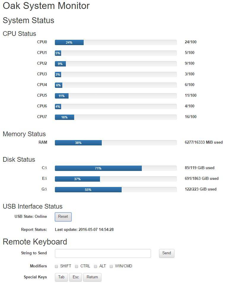
There are sections in the HTML that I mark with unique "id" values. That way, I can fill them in later, after I've gotten the latest report from the Oak. Most of the HTML in this is just for layout purposes, and all the data will be inserted into the layout later in JavaScript.
function reportSuccess(json) {
  if(json == null || typeof json !== 'object') {
    $("# rpt-status").html("Invalid response from Oak!");
    setTimeout("getReport()",3000);
    return;
  }
  if('t' in json) {
    $("# rpt-status").html("Last update: "+json['t'])
  } else {
    $("# rpt-status").html("No update timestamp!");
  }
  if('c' in json) {
    var output = ''
    for(var i in json['c']) {
      output += buildProgressBar("CPU"+i, json['c'][i], 100, "")
    }
    $("# status-cpu").html(output)
  }
  if('m' in json) {
    var output = ''
    var used = (json['m']['t']-json['m']['a'])/(1024*1024)
    var total = json['m']['t']/(1024*1024)
    output = buildProgressBar("RAM", used, total, "MiB used")
    $("# status-mem").html(output)
  }
  if('d' in json) {
    var output = ''
    for(var i in json['d']) {
      var used = json['d'][i]['u']/(1024*1024*1024)
      var total = json['d'][i]['t']/(1024*1024*1024)
      output += buildProgressBar(json['d'][i]['m'], used, total, "GiB used")
    }
    $('# status-dsk').html(output)
  }
  setTimeout("getReport()",3000);
}

function reportError(xhr, status, error ) {
  $("# rpt-status").html("Error in the response from the Oak!");
  setTimeout("getReport()",3000);
}

function getReport() {
  $.ajax("/report", {
    success:reportSuccess,
    error:reportError
  })
}
This chunk of code is responsible for requesting and displaying the PC's report. We generated this report a loooong time ago in the Python code, shuffled it between two boards in Processing, and finally we're fetching it to the client browser here.
It all starts with getReport, which uses jQuery's ajax functionality to make an asynchronous request to the Oak. The Oak (hopefully) responds with a valid report, and then the reportSuccess function is called.
Design Decision Note that I don't set a timer to call getReport again until after the Oak has responded. The ESP8266 is not a high performance web serving device by any stretch of the imagination. By waiting until the request finishes before ever thinking about starting a new one, the ESP8266's web server doesn't get backed up with requests.
In reportSuccess, the JSON response from the Oak is parsed out, and HTML is generated to show the results to the user. I have a helper routine called buildProgressBar that makes a nifty little progress bar out of data like CPU usage. After processing each section of the JSON, I write the output HTML into the div element whose ID corresponds to that section in the HTML.
  $("# kbd-send").click(function (e) {
    $.ajax('/kbdstr',{
      method: 'POST',
      success: onKbdSuccess,
      data: {mod:getMod(), str:$("# kbd-str").val()}
    })
  })
The buttons are assigned function callbacks in the $(document).ready() handler. This handler runs once the page is ready, so just one time after everything on the page has initialized. Here again, I use the ajax functionality of jQuery to send the request to the server. The data field in the ajax call sends parameters to the server that I can read in the Oak's code. Here, I'm sending the mod parameter with the keyboard modifier boxes that have been checked, and the str parameter with the characters typed into the input blank.
Security Warning Just a reminder that if you are at all concerned about security (and for pete's sake, you SHOULD BE!) this is a terrible idea to make a keyboard accessible over WiFi. Once SSL is supported by the ESP8266 Arduino libraries, and if you can come up with an authentication scheme to block unwanted users, this will become less of a security issue. For now, either don't use this part of it (ie, comment out the Pro Micro code) or use at your own risk!
# Conclusion & Next Steps
There are a few things I still need to do on this build:
I'd like to be able to put the PC to sleep via the Pro Micro. I think this should be possible by extending the USB HID descriptor so that it supports the "Sleep" key found on some multimedia keyboards. I just haven't gotten around to parsing the USB HID spec and figuring out exactly how to extend the descriptor in the Arduino's keyboard library. Waking the PC up is no big deal, just reset the Pro Micro via the web interface.
Security is still at the top of my mind, and I wish I could easily address it. SSL and a password on the Oak's web interface will make this somewhat more secure, but having a keyboard accessible via WiFi is always going to be a bit of a security risk.
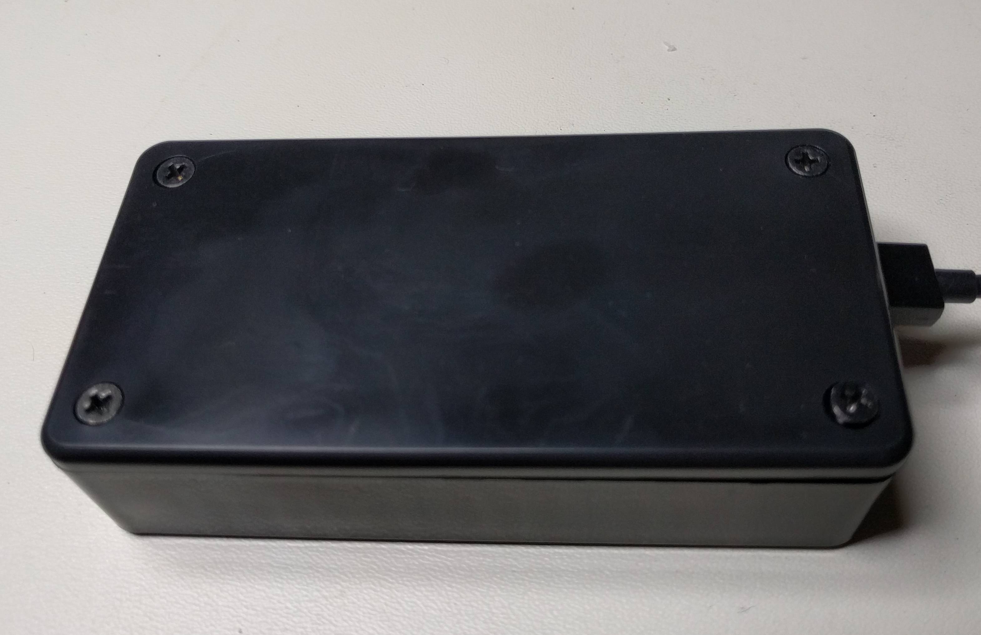
I did a crappy job of cutting the case, it's all sorts of wonky. This thing will be hidden behind other cables, wires, etc, so it's not a huge deal, but I do need to just take my time or perhaps just break out the Dremel next time.
I've done my best to summarize all the hardware and software involved in this build. No doubt there are areas I've glossed over in the previous 5,000 or so words, so feel free to ask questions and I'll do my best to answer.